 |
|
|
|

back
|
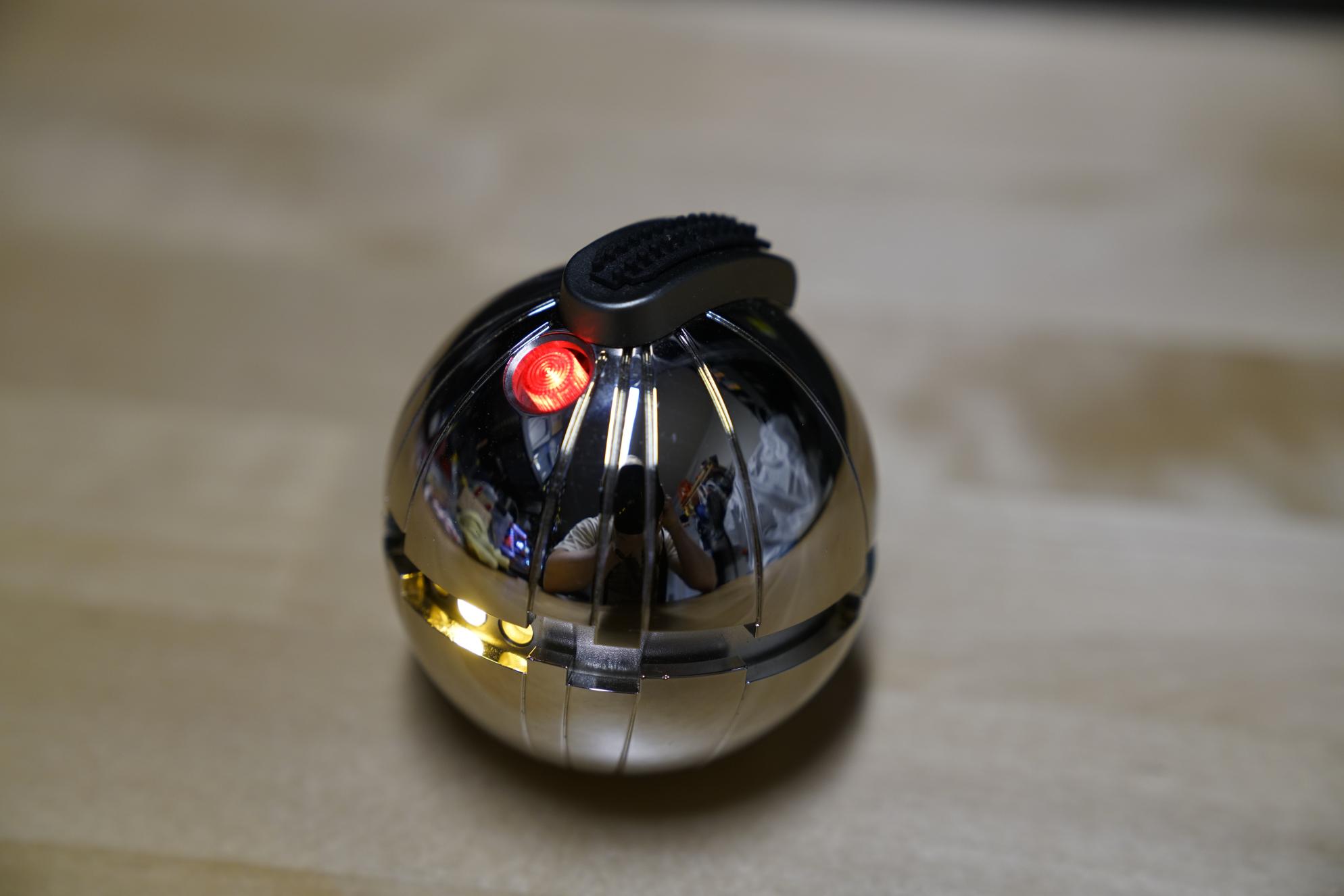
Proffieboard Thermal Detonator
|

|
for the discerning bounty hunter
 What you'll need:
Additional resources
What you'll need:
Additional resources
The helper PCB
The helper PCB has many jobs: It holds the switches in place, reduces cable clutter and adds a timeout to cutting the power
when the detonator is switched off.
To assemble the helper PCB, start with the SMD components. You can either use the reflow skillet method or just hand-solder them. If you hand-solder them, I recommend applying liquid flux, then hold the part in piece with some tool, then add a little bit of solder to the iron and transfer the solder to the pad. Next, move on to the switches. Make sure the LED in the illuminated switch is inserted the right way. The positive side of the LED has a longer LED and should be on the side of the switch closest to all the POW pad. Finally, make sure to snip the pins from the switches on the back of the board so they aren't in the way.
I recommend doing the front LEDs last and solder them in-place after everything is in the right place in the chassis.
Making the button move
As shipped, the red LED cover doesn't really move. To fix that, I used a combination of filing the metal holder slightly,
and scraping away a little bit of plastic from the red part itself. Basically I just scored the plastic all the way around
with a knife, about 1mm above the edge, then I cut and scraped away the extra plastic between the scored line and the edge.
I also had to sandpaper a little bit from the bottom to make everything fit together properly. Do not snip off the bottom part of the red button as shown
in Khal's video.
Wiring everything up
This diagram shows all the connections that need to be made with wires.
Some of the connections are best made after the boards are in place to make sure the wires are as short as
possible. However, the connections on the battery, the connections on the proffieboard and all the connections on the
side of the helper board needs to be made before putting things in place, or you'll have a difficult time and/or
melt a buch of plastic. The four connections in the middle of the helper board are intended to be made by threading
the cables through the bottom of the board and soldering the top to save space, however doing it the other way works
too, it just makes the space in the detonator a little more cramped. The next section will explain in which order to do things.
Putting it together
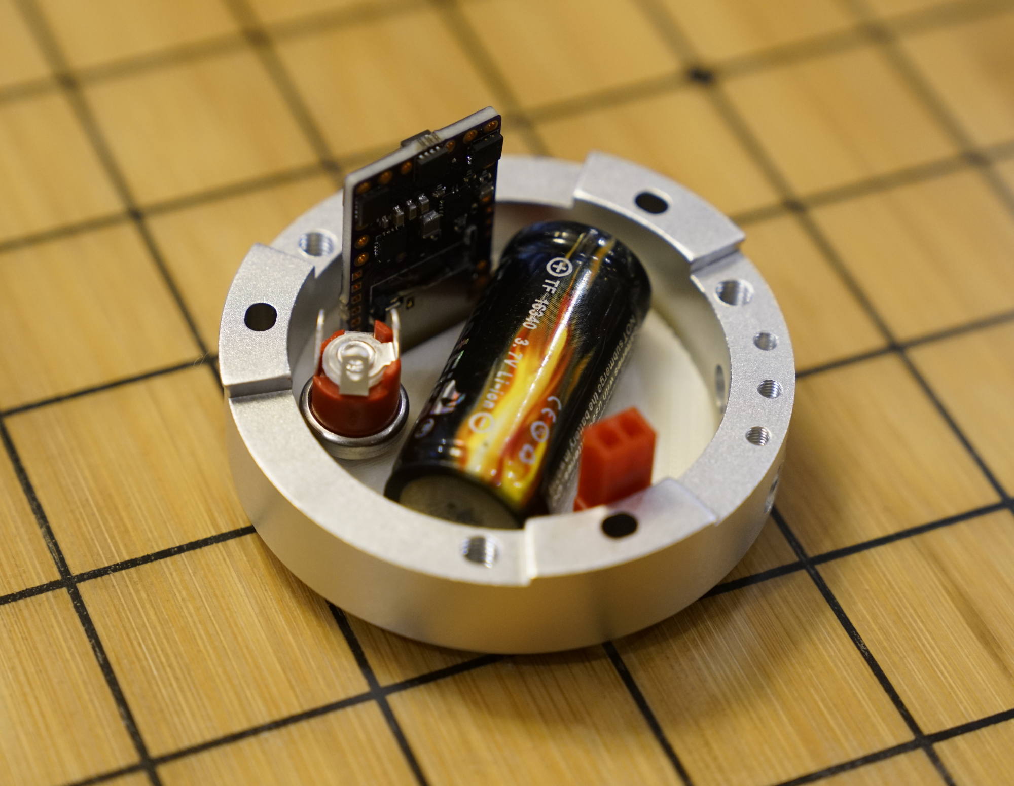
The chassis most of the parts gets mounted inside the mounting ring.
This picture shows what it looks like on the inside.
 Here is the approximate order for putting things together:
- Glue the tank tread to the top slider.
- Put all the spring loaded grub screws into the mounting ring and adjust them.
- Screw the top slider to the inside part. (Not the one that came with the kit.)
- Attach wires to the battery
- Solder wires to the side of the TD helper.
- Solder the four center wires to the bottom of the TD helper.
- Shorten the ears on the exciter, attach wires and crimp to female JST connector.
- Use the attached 3m glue pad to glue the exciter to the bottom part of the detonator.
- Crimp cables into the male JST connector
- Screw the recharge port into the bottom part of the chassis.
- Mount the three front LEDs into mounting ring, DO NOT cut the legs. Make sure that the long leg is to the right when seen from above. Bend the legs upwards.
- Put the bottom chassis part in the mounting ring.
- Put the battery in.
- Put the male JST connector in.
- Slide the TD helper into the top chassis part, let it stick out a little towards the front.
- Fit the legs of the three front LEDs through the holes in the front of the TD helper.
- Place the top chassis part on top of the mounting ring. (Will take a little wiggling)
- Solder all the wires to the proffieboard, leave a little extra.
- Slide the proffieboard into it's slot. (More wiggling, possibly some filing)
- Solder the charge port wires, use the positive side to link the wires from the helper and the battery.
- Solder the front LED pins and clip them.
If you did it all correctly, it should look something like this:
 The rest of the the assembly follows the regular assembly instructions, with the exception of adding some M3 washers
to the screws that hold the shells together to create a little extra space inside.
The rest of the the assembly follows the regular assembly instructions, with the exception of adding some M3 washers
to the screws that hold the shells together to create a little extra space inside.
Preparing the SD card
While it is possible to use the Thermal-D font as is, it isn't really set up to to work the way I wanted it to.
So here is what I did to make it work they way I wanted it:
- Create a directory called "tdmod"
- Copy boot.wav, poweroff.wav, poweronf.wav, poweron.wav, pwroff2.wav, clash5.wav from Thermal-D to tdmod
- Copy Thermal-D/clash1.wav to tdmod/boom1.wav
- Copy Thermal-D/clash2.wav to tdmod/boom2.wav
- Copy Thermal-D/swing1.wav to tdmod/hum.wav
- Run the following command: sox --combine=concatenate
"|sox clash5.wav -p trim 110s 2442s"
"|sox -n -r 22050 -p trim 0 0.3"
"|sox clash5.wav -p trim 110s 2442s"
"|sox -n -r 22050 -p trim 0 0.3"
"|sox clash5.wav -p trim 110s 2442s"
"|sox -n -r 22050 -p trim 0 0.3" -b 16 bgnarm.wav
- Run the following command: sox --combine=concatenate
"|sox clash5.wav -p trim 110s 2442s"
"|sox -n -r 22050 -p trim 0 0.05" -b 16 armhum.wav
- delete tdmod/clash5.wav
Now copy the tdmod directory to the sd card, and it should work in a way that makes more sense to me.
Installing the software
Installing ProffieOS is the same as for a saber, here is a config file to get you started:
#ifdef CONFIG_TOP
#include "proffieboard_config.h"
#define NUM_BLADES 2
#define NUM_BUTTONS 2
#define VOLUME 2500
const unsigned int maxLedsPerStrip = 144;
#define CLASH_THRESHOLD_G 2.0
#define ENABLE_AUDIO
#define ENABLE_MOTION
#define ENABLE_WS2811
#define ENABLE_SD
#define DELAYED_OFF
#endif

#ifdef CONFIG_PROP
#include "../props/detonator.h"
#endif

#ifdef CONFIG_PRESETS
Preset presets[] = {
{ "tdmod", "tracks/laptinek.wav",
   StylePtr<InOutHelperTD<SimpleClash<ColorSequence<2000,
	     Rgb<255,0,0>,Rgb<255,255,0>,Rgb<255,0,255>,
	     Rgb<0,255,255>,Rgb<0,255,0>,Rgb<0,0,255>,
	     Rgb<255,255,0>,Rgb<0,255,255> >,
	  RandomFlicker<WHITE, BLACK>, 6000, EFFECT_BLAST>, 100, 100, 6000, BLACK>>(),
  StylePtr<InOutHelperTD<Lockup<SimpleClash<RED,RandomFlicker<RED,BLACK>, 6000, EFFECT_BLAST>,
           Pulsing<RED, Rgb<50,0,0>, 300>>, 100, 100, 6000>>(),
""},
{ "ThermalD", "tracks/cantina.wav",
  StyleRainbowPtr<100, 100>(),
  StylePtr<InOutHelper<Lockup<RED, Pulsing<RED, Rgb<50,0,0>, 300>>, 100, 100>>(),
  ""},
};
BladeConfig blades[] = {
{ 0,
  SimpleBladePtr<CH1LED,CH2LED,CH3LED,NoLED, bladePowerPin1, bladePowerPin2, bladePowerPin3, -1>(),
  SimpleBladePtr<CH1LED,NoLED,NoLED,NoLED, bladePowerPin4, -1, -1, -1>(),
  CONFIGARRAY(presets) },
};

#endif

#ifdef CONFIG_BUTTONS
InvertedLatchingButton PowerButton(BUTTON_POWER, powerButtonPin, "pow");
Button AuxButton(BUTTON_AUX2, aux2Pin, "aux");
#endif
Problems? Questions? Suggestions? Check out The Crucible.
This page has been accessed 16,109 times since
July
8th,
2019.
Last modified:
March
29th,
2021
- Design by
Monica &
Fredrik
Hübinette
|
|
|
|
|