 |
 |
 |
 |

back
|
Teensy Saber V2 Test Rig
|

|
DIY Teensy based lightsaber
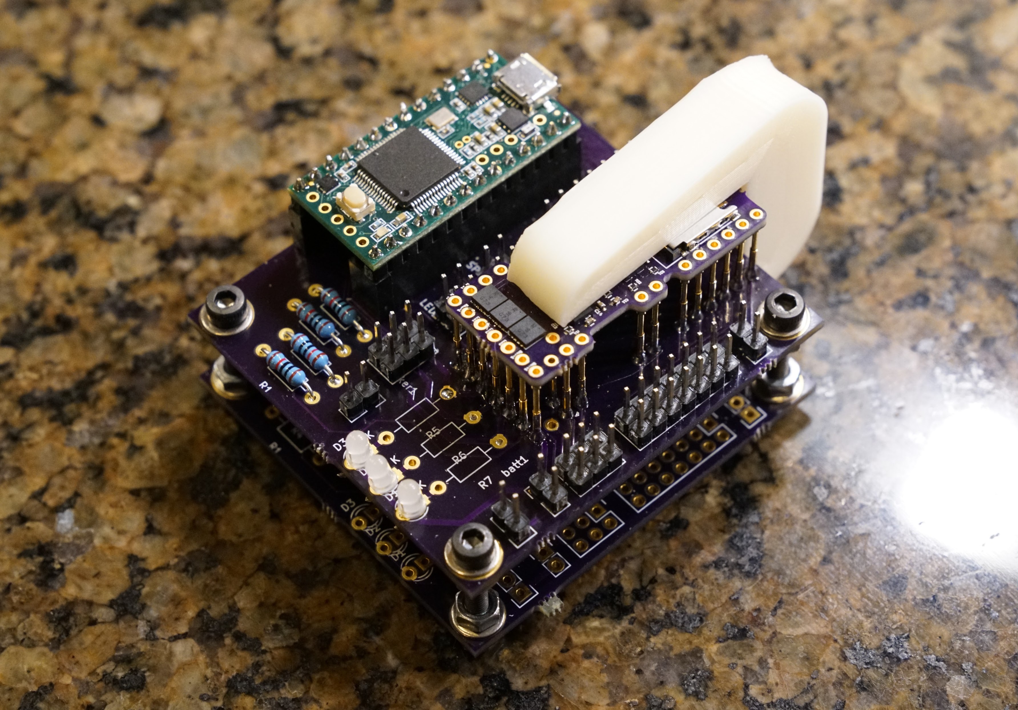
This test rig allows you to test a TeensySaber V2.x board without
having to solder it to a Teensy.

Download TeensySaber V2.x test rig KiCad files here.
What you will need:
Assembly
Assembly is pretty straightforward. Solder all the headers, resistors and LEDs into place and trim the legs.
Screw two PCBs together with the 20mm screws. The one with all the components on it goes on top. The bottom
one is left completely unpopulated. Insert the pogo pins and solder them to the top board. Solder some pin
haders to a Teensy 3.2, matching the female headers on the board. Put the Teensy in place and flash the
TeensySaber firmware on it.
Caveats
There are several things that could be improved on this test rig, but the most important one is that
there is quite a lot of crossover between audio and sd card communications. This leads to some hiss and
distortion, so this setup does not work for evaluating sound quality.
Pinout
 All the pins that DON'T have an asterisk should normally be jumpered. The yellow outlines show where to put the female headers.
For the pins that do have an asterisk, keep reading:
- 5v - this connects the 5v produced by the teensysaber board with the 5v pin on the teensy. Do not bridge this while
your teensy is hooked up to an USB connection unless you have cut the vin-vusb apart on your teensy. (I don't recommend
cutting the vin-vusb on your testing teensy though.)
- Battery - This is where you plug in a single ~3.8v power source. Unfortunately the polarity is not marked on the board.
- Power - Bridge this to turn power the booster and audio (and the teensy if you have the 5v jumper.)
- Audio Test - Allows the teensy to sense the output from the amplifier with analogread. There is no code that utilizes this at this time, so leave it open.
- LED test - Allows the teensy to sense the output from the FETs. There is no code that utilizes this at this time, so leave it open.
Test procedure
- Before you put the TeensySaber board on the test platform, measure the resistance between
BATT+ and BATT-. If the resistance is basically zero, it might burn the traces on the test rig when
we plug in a battery. Check the resistance between BATT+ and GND the same way.
- Insert a formatted SD card with some wav files on it.
- Make sure the battery is disconnected from the test rig.
- Put the teensysaber board on the pogo pins, press down and use the clip to hold it in place.
- Connect the battery.
- If your teensy is powered by usb, you should reboot it. (Either type "reboot" in serial monitor, press program button, or unplug usb temporarily.)
- Try "on", "off", "beep", "dir", "monitor motion", "batt" and "play somefile.wav" commands.
- If they all work, and behave as expected, the board is working.
- Disconnect batter.
- Rermove board.
Problems? Questions? Suggestions? Check out The Crucible.
This page has been accessed 5,407 times since
April
10th,
2017.
Last modified:
March
29th,
2021
- Design by
Monica &
Fredrik
Hübinette
|
 |
 |
 |
 |

