This test rig allows you to test a Proffieboard without
having to solder a bunch of wires to it.
You may want to check out the new test rig which can handle
both V1 and and V2 proffieboards.
a toggle clamp, some pieces of wood and some bolts to hold the board in place on the pogo pins
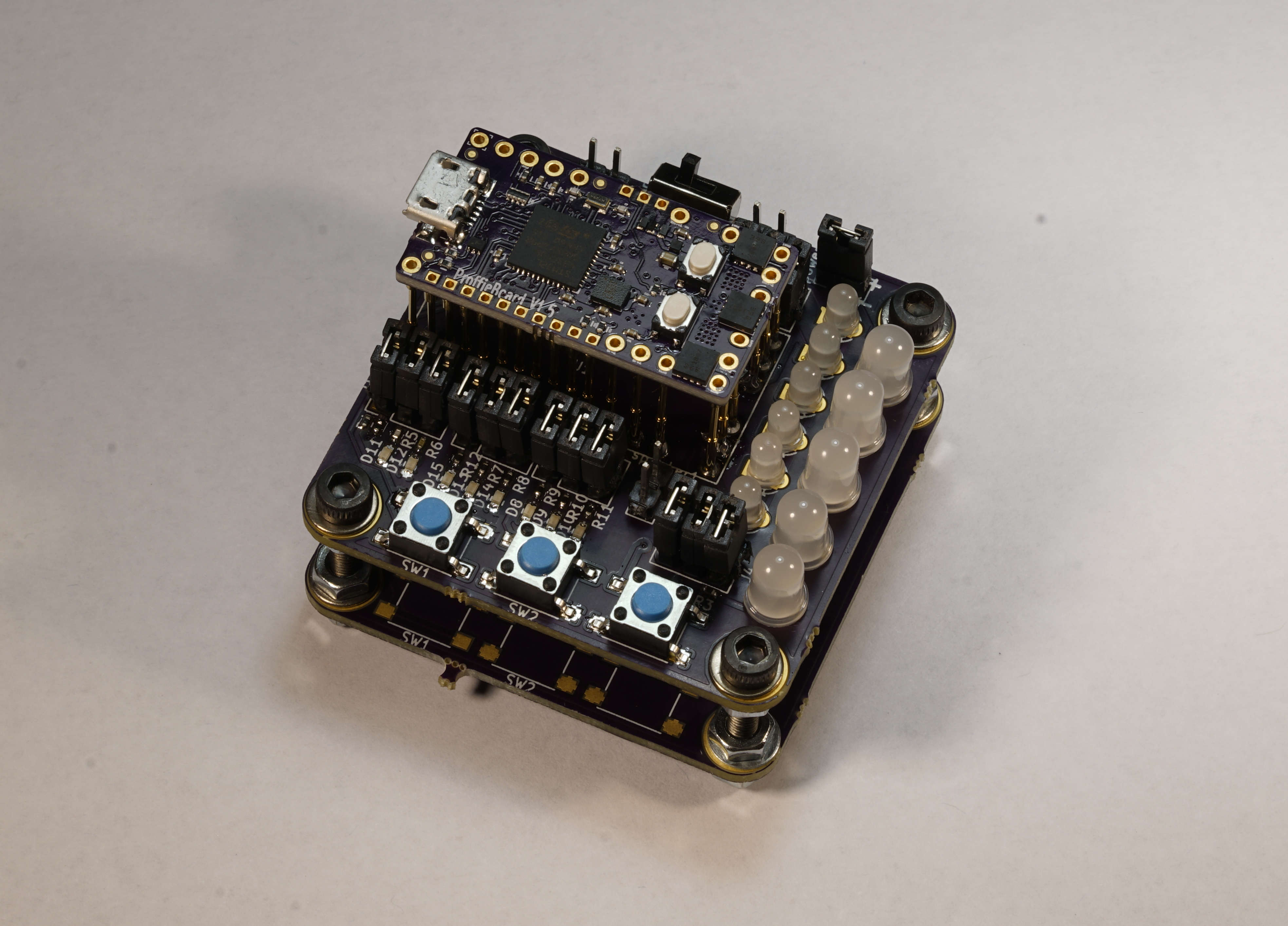
Assembly
Assembly is pretty straightforward. Start with the SMD components, then solder all the headers, buttons and LEDs into place and trim the legs. Note that some of the labelling on the board itself is not very good, just know what the two resistors closest to the edge are 10k, R3 is 300 ohms and the rest are 2.2k. Also, the +/- labelling on the power connectors are messed up. The + pin is the one closest to the switch.
Screw two PCBs together with the 20mm screws. The one with all the components on it goes on top. The bottom
one is left completely unpopulated. Insert the pogo pins and solder them to the top board.
Pinout
Normally, you'll want to place jumpers all down the left side of the board. Where it says J1, J2, J3. This connects the output pins to LEDs so you can see what is going on. Most of the time I have J4 and J5 jumpered as well, as that hooks up the 6 LEDs and lets me do basic testing. I usually leave the neopixel jumper out, as the neopixels blink distractingly otherwise. The two sets of power pins are interchangable, and the switch decide which of them actually powers the board. I hook up one of them to a multimeter, and set the multimeter to beep if there is a short, and I hook up the other one to a 3.7v 18650 battery. The idea is that the multimeter will tell you if there is a short, before you power everything on. If you plug in the battery to a board that has a short, it will most likely fry the test rig. (Don't ask how I know that.)
Test procedure (for linux)
In one window, start up OpenOCD
In a second window, run tail -f /var/log/kern.log
Start up arduino and enable test script in lightsaber.ino
Hook up a multimeter to test board and set it to beep on a short. Verify that this works!
Now, for each board:
Insert SD, put board on test rig and plug in USB.
Check that OpenOCD connects and that kernel window says STM32 bootloader
press reset, make sure STM32 bootloader pops up again
It should say LOW BATTERY repeatedly, no beeps
Switch to battery power
Press BOOT
Press Power button
Press AUX button
Press AUX2 button
verify that all LEDs light up in order
verify that music is playing
Switch back to short checking and turn off USB
Problems? Questions? Suggestions? Check out The Crucible.
This page has been accessed 8,448 times since
July
30th,
2018.
Last modified:
March
29th,
2021
- Design by
Monica &
FredrikHübinette
