 |
|
|
|

back
|
Proffieboard V1/V2/V3 Test Rig
|

|
DIY Teensy based lightsaber
This is a breakout board that makes it easy to test a
Proffieboard without having to solder a bunch of wires to it.
Download Proffieboard breakout board kicad files here.
What you will need:
- V3 Breakout PCB
- Optionally, a stencil (download kicad file, export gerbers, and upload to oshstencils, or use a vinyl cutter)
- All the parts from the BOM
Assembly
Start with the SMD components. Either use a stencil to spread the paste,
or dot solder paste on the pads manually. Then place the SMD components.
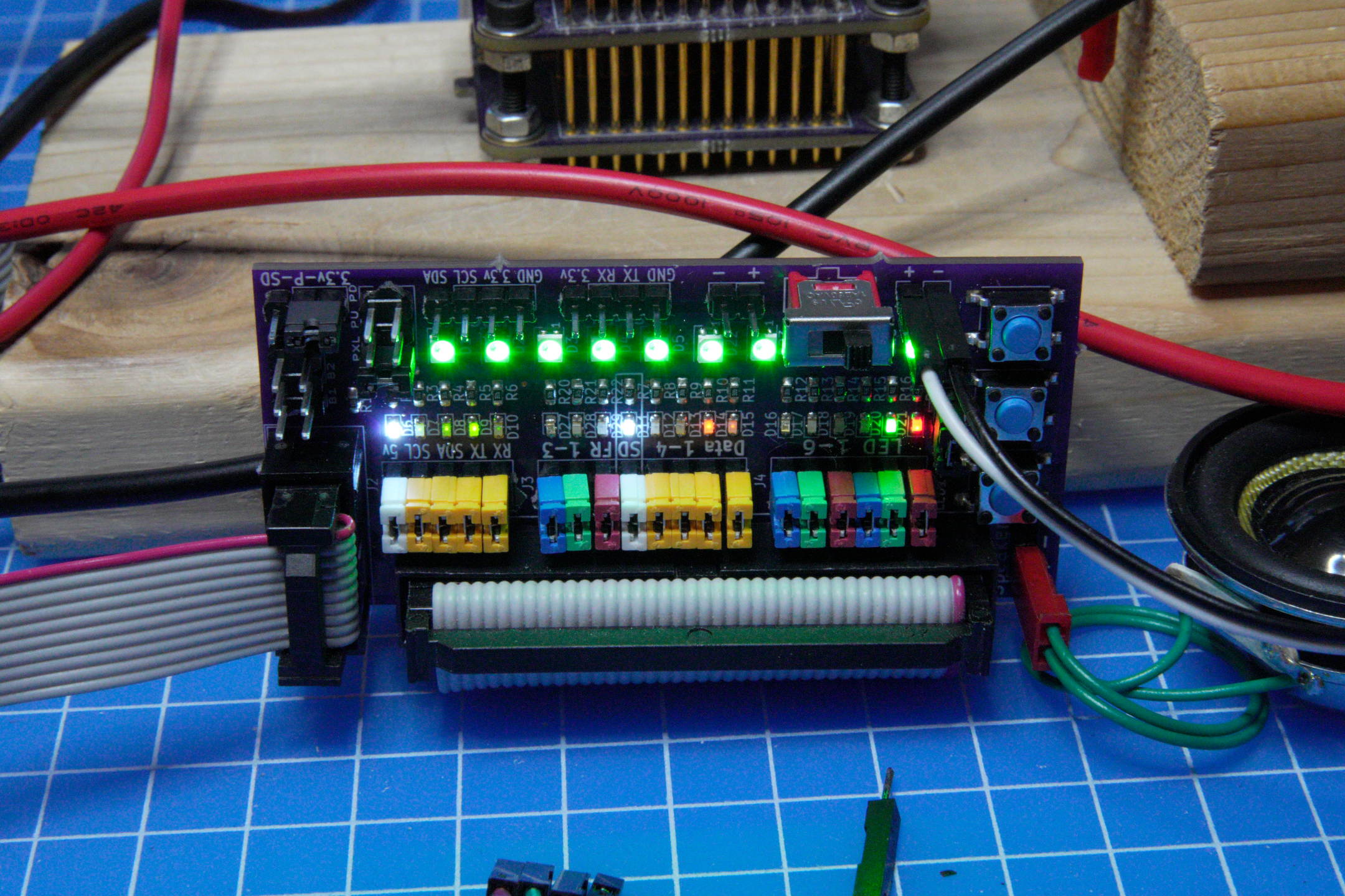
Note that the six LEDs for "LED 1-6" are
placed in the opposite direction compared to the other LEDs. Also, beware
that the resistor next to 5V LED is 3.3k, while the rest of them are 2.2k.
Please note that you can use any color LEDs you want, I used a variety in the one above to make it easier to see which LED is lighting up.
When all the SMD components are in place, either use a reflow oven (or skillet) or a hot-air rework station to melt the solder paste.
Next do the switches, pins and headers. All of which are standard through-hole components.
Pinout
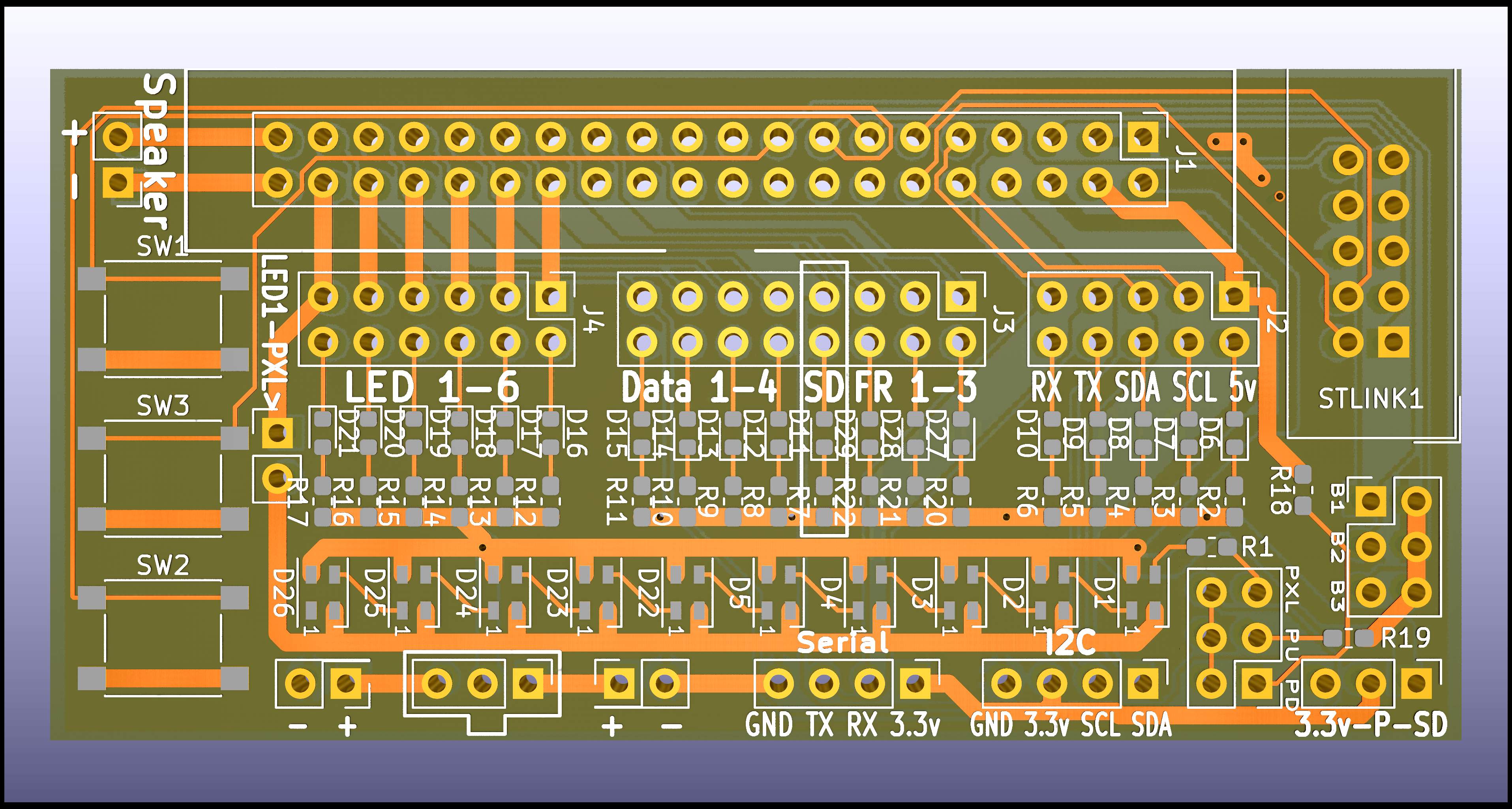 All the inputs/outputs are labelled on the board. Here is a description of what they all do:
- TOP
- Speaker: Speaker (duh)
- Main connector (to pogo pins)
- Stlink1: This lets you hook up an ST-Link V2 using a 10-pin ribbon cable.
- MIDDLE
- SW1/2/3: Buttons (pow/aux/aux2)
- LED1->PXL> : Jumper this to have LED1 power the pixels on the board.
- Led 1-6: Led pad 1-6
- Data 1-4: pixel data output 1-4
- SD_VDD (data 5 on V1 boards)
- Free 1-3: PWM/Button/Servo/accent LED 1-3 (For V3 boards only)
- RX/TX: Serial Port
- SDA/SCL: I2C Port
- B1/B2/B3: Button pins
- BOTTOM
- Battery input 1 (+/-)
- Power switch
- Battery input 2 (+/-) normally used to check for shorts
- Serial: For bluetooth modules
- I2C: For hooking up oled display
- D1 select: These three jumpers lets you decide what is hooked up to data 1. PU = 10k pullup, PD = 10k pulldown, PXL = pixels
- 3.3v-P-SD: This lets you select where the Serial and I2C connector source their 3.3 volts from. Putting a jumper from 3.3v to P will take it from the 3.3v pad, and if you put the jumper between P and SD, it will take it from the SD power output. (V2 board only)
Problems? Questions? Suggestions? Check out The Crucible.
This page has been accessed 2,809 times since
May
24th,
2021.
Last modified:
May
13th,
2023
- Design by
Monica &
Fredrik
Hübinette
|
|
|
|
|