This is version 1 of the teensy saber electronics. It can be made entirely from parts you can easily buy, and uses big FETs which can control a LOT of current. However, it is fairly bulky compared to other lightsaber solutions. You might want to take a look at version 2 which is much smaller, but harder to make. (But maybe you can just buy one.) What you will need:
Circuit diagram 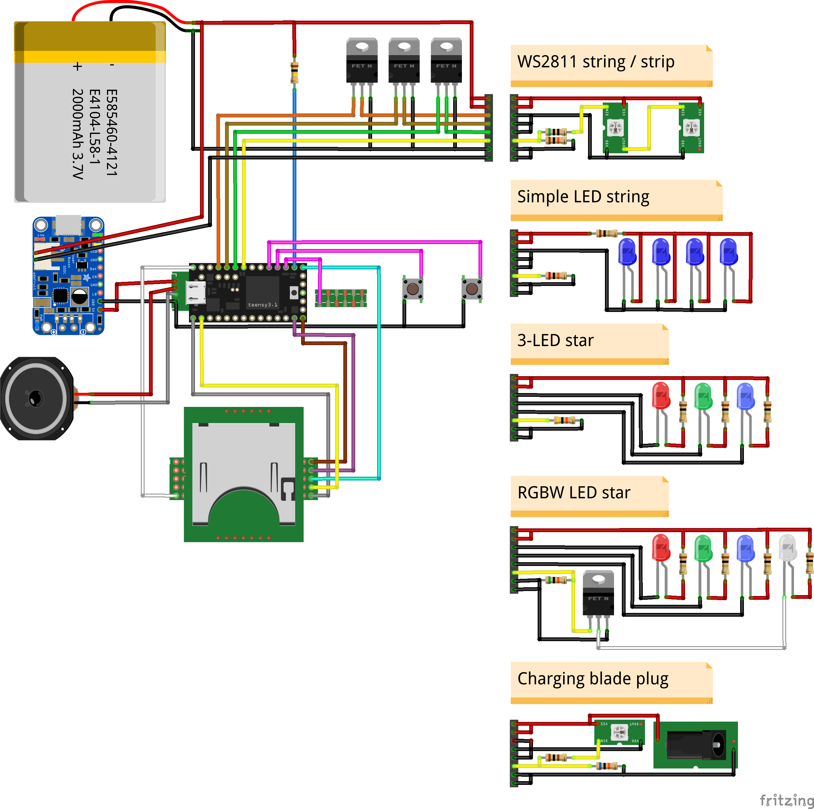
Important! Make sure you cut the lead between VIN and VUSB on the teensy before you solder it to the prop shield. Cutting it afterwards is not nearly as fun. (But possible with a dremel and small engraving bit.) Once VIN/VUSB is cut, you'll need to provide external power to use and program the teensy. Also, DO NOT connect the 3.3v pads on the sd card adapter. It's easier to just feed it 5 volts. Now place pin headers on the prop shield in the following locations: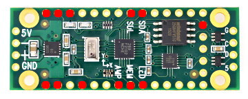 place pins in slots marked with red Then put the teensy 3.2 on top of the prop shield and turn it over. Now, carefully push the pins with a metal tool until they are flush with the bottom of the prop shield. If we don't do this, the pins will not be long enough to attach the sdcard adapter. (Thus, if you're not using the sdcard adapter, feel free to skip this step.) Solder all the pins into place, both on the bottom of the prop shield and on the top of the teensy. Now we need to cut "pin 2" because we don't want it to connect to the SD card adapter. 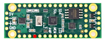 pin 2 Next, cut three short wires, strip the ends and solder them to the MISO, MOSI and CLK on the sd card shield. Put the sdcard shield in place (but don't solder it yet). These wires are going to connect to pin 12, 11 and 13 on the teensy AND the prop shield, so cut and strip them to length, make sure that you strip enough that the cable can go through the teensy and down to the prop shield, then solder the wires in place, both on the bottom of the prop shield and on top of the teensy. Now, solder the sdcard into place. 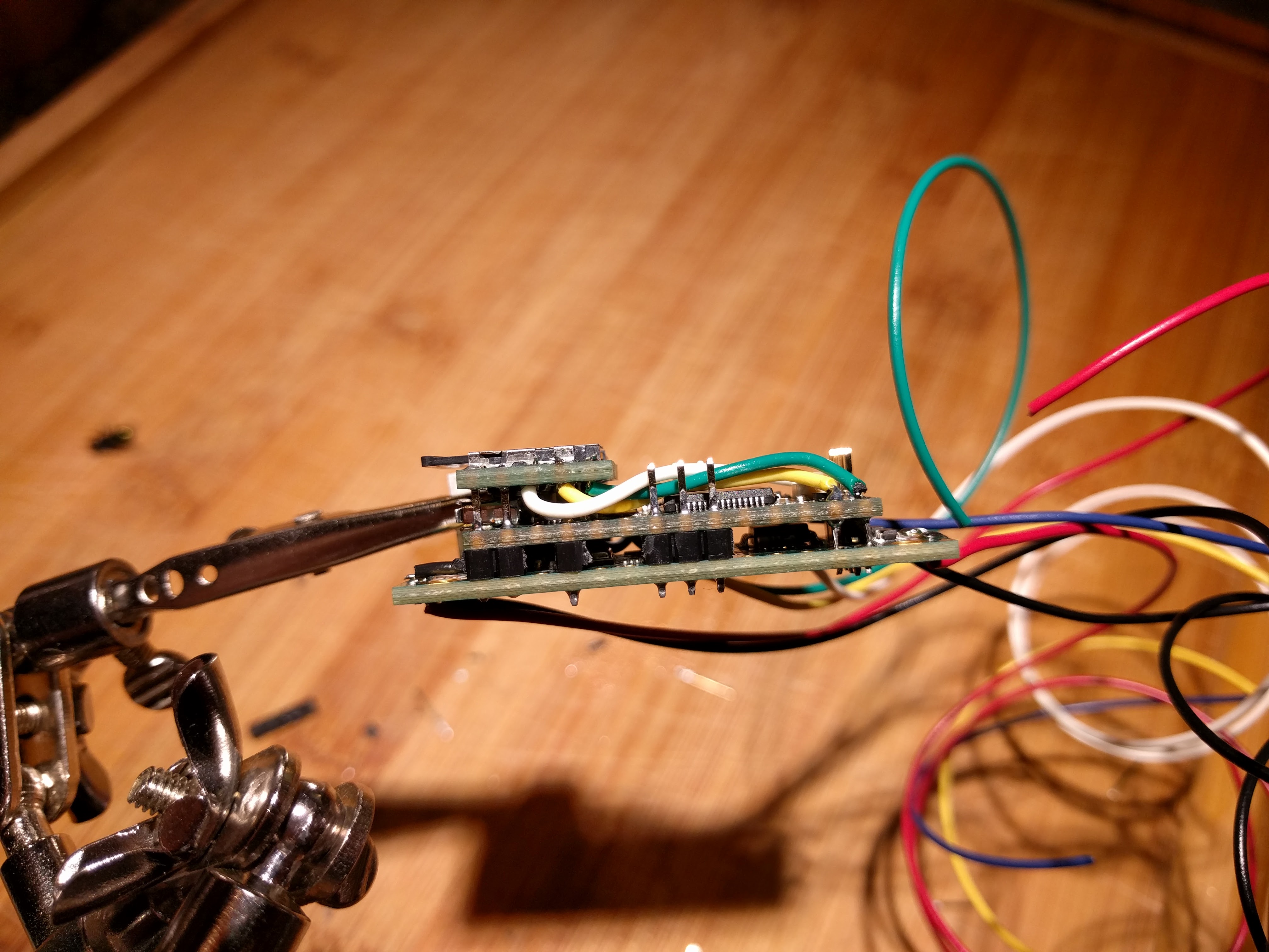 I later replaced the wires with thinner 30-gauge wires, which works better. I recommend bending the pin at the "A14 / DAC / Audio In", this will keep it from poking into the battery, while still protecting the reset switch from getting pressed accidentially. The other pins will probably need to be cut down a bit to fit. But again, it's probably better to not cut them too short, as that makes it more likely that the reset switch will be pressed accidentially. The FETs can be arranged any way you want, I cut a small 2x13-hole proto board to hold the FETs. I used the spaces in between the FETs as power bus connectors, one for the positive side and one for the negative side. The sparkfun lipower power booster is the smallest I could find, still it was too big before I removed the battery connector and soldered in wires instead. Once I did that, it fit snugly to the side of the teensy/prop shield/sd card sandwich, which made the whole thing fit better. I also found that the capacitor hooked up to the under-voltage lockout pin causes problems if the voltage suddenly drops by as little as 160mV, which happens all the time when you turn the saber on. To fix this problem, remove the capacitor shown here: 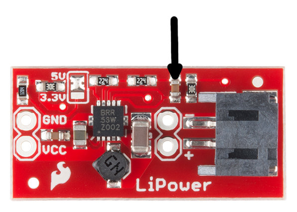 The rest is all done with wires, I recommend thin 28/30-gauge wires for all the cables that connect to the teensy and it's power booster. The wires that carry power to and from the FETs should probably be a little beefier, about 24-guage or so, anything too big is going to take up too much space. When it's all hooked up, it should look something like this: 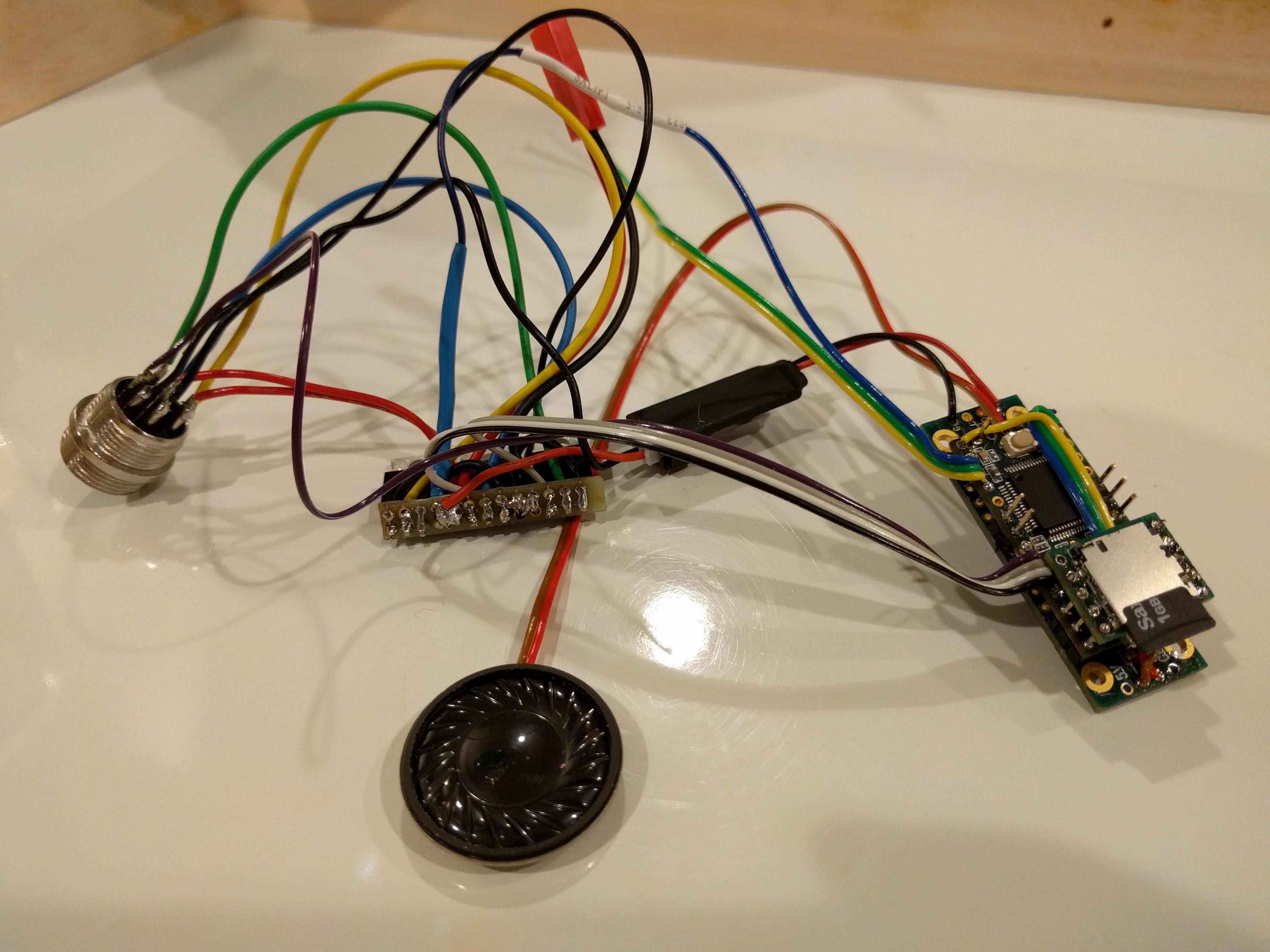 This was before I removed the connector from the booster.
A note about batteries
Other options
Troubleshooting Problems? Questions? Suggestions? Check out The Crucible. Last modified: March 29th, 2021 - Design by Monica & Fredrik Hübinette |
|||||||||||
