This helper board has three functions, and you choose which ones you want to use. All three functions requires the GND pad to be connected to GND on the board. 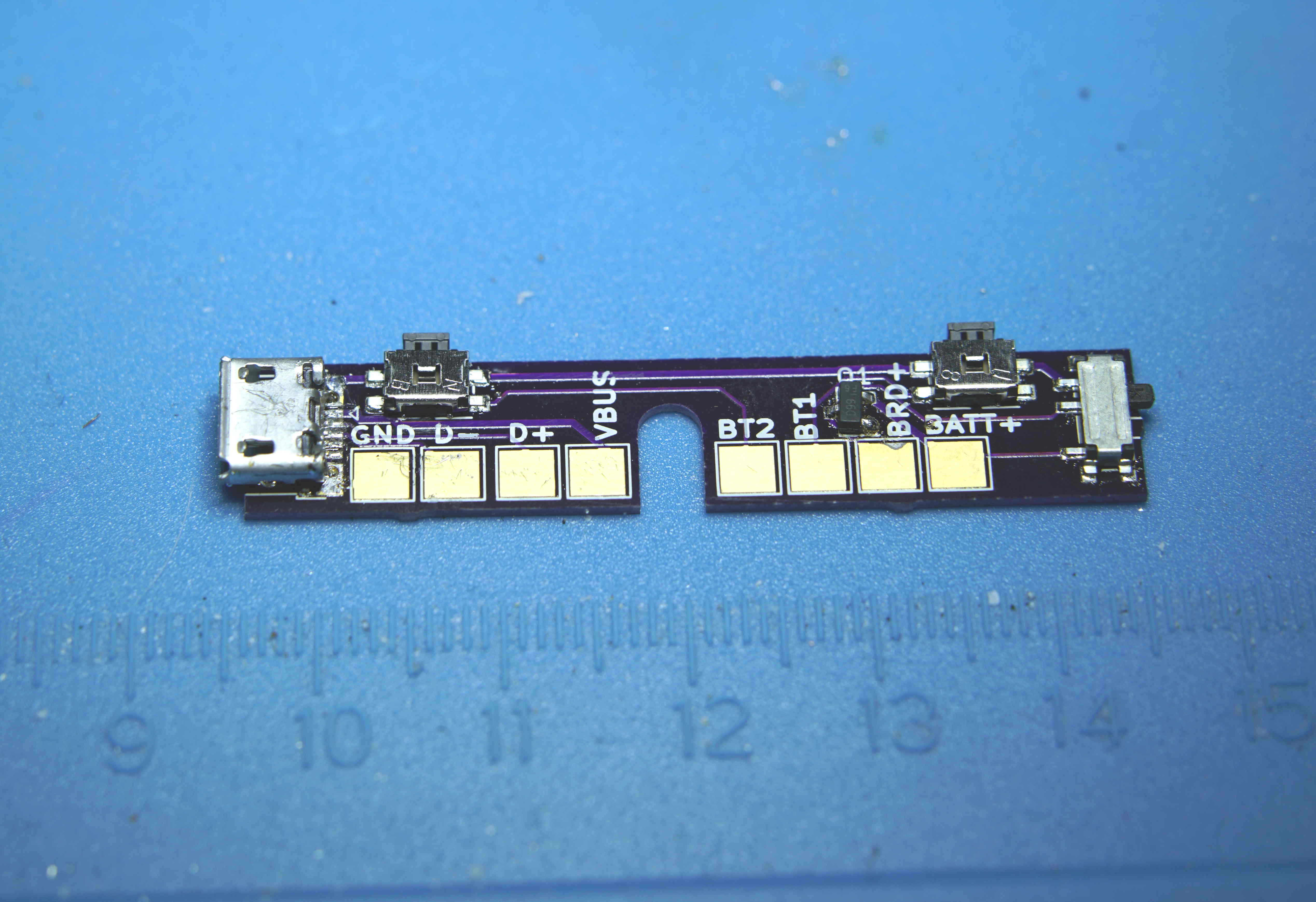
ButtonsFor this function, you need one or both of the buttons mounted on the board. Then the button pads can be connected to the BT1 and BT2 pads on the board. For my saber, I don't actually use the buttons, because there are buttons on the side of the saber.
USB extensionFor this function, the USB connector needs to be connected to the board. I recommend wiring up GND, D+, D- and VUSB to an USB plug, but if you're really low on space, it is possible to remove the USB connector from the Proffieboard and solder wires directly to the pads underneath. Beware that this requires a high degree of soldering skills.
Kill SwitchTo use the kill switch, the pFET is also needed.
AssemblyAssembly is pretty straightforward, I recommend using the reflow skillet method, but a hot-air reflow station will also work. Just make sure you test everything, especially the USB connections as they are prone to shorts.
SchematicProblems? Questions? Suggestions? Check out The Crucible. Last modified: March 29th, 2021 - Design by Monica & Fredrik Hübinette |
|||||||||||
