 |
|
|
|

back
|
Teensy Saber Electronics V2
|

|
open-source lightsaber shield
 The V2 design is now superceeded by the V3 design.
Unlike all the V1 TeensySaber electronics, the V2 board is not
something I recommend that most people build themselves. All the
instructions for doing so are available here,
but most people should just continue reading to find out how to use
the board.
What you will need:
Putting it together
Important! Make sure you cut the lead between VIN and VUSB on the teensy before you solder it to the TeensySaber V2. Cutting it afterwards is not nearly as fun. (But possible with an exacto knife or similar.) Note that after you cut VIN/VUSB, you'll need to provide external powre to use or program the teensy. Once attached to to the TeensySaber, it will draw power from the battery to power the Teensy.
 Once that's done you need to solder your TeensySaber to a Teensy. For a Teensy 3.2, here is where you place all the pins:
 Note, if you're using a Teensy 3.5 or 3.6, you need to move the audio in pin (see pinout diagram below).
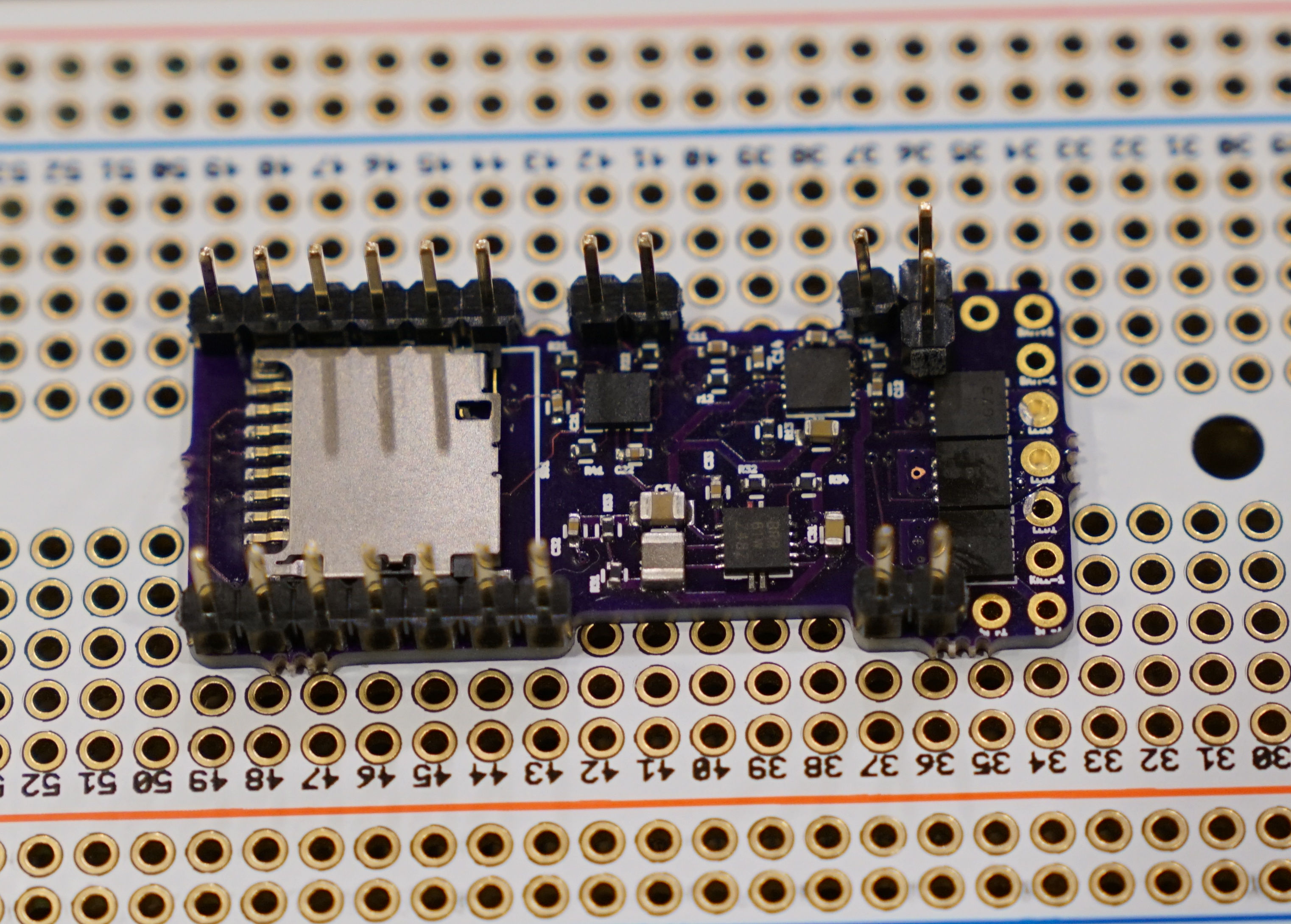
The easiest way to solder the teensy to the teensysaber board is to use header pins.
However, once joined in this way, it's quite difficult to get them apart again, which means
that if one of the boards develop a fault, you pretty much have to throw away both of them.
What I recommend doing is to use header pins only in two corners, then use some regular wire
for all the other connections, that way you can cut the wires and desolder everything fairly
easily should you need to. (Full disclosure: I have not tried this yet, but I have ruined
a few boards while trying to get the pins out...)
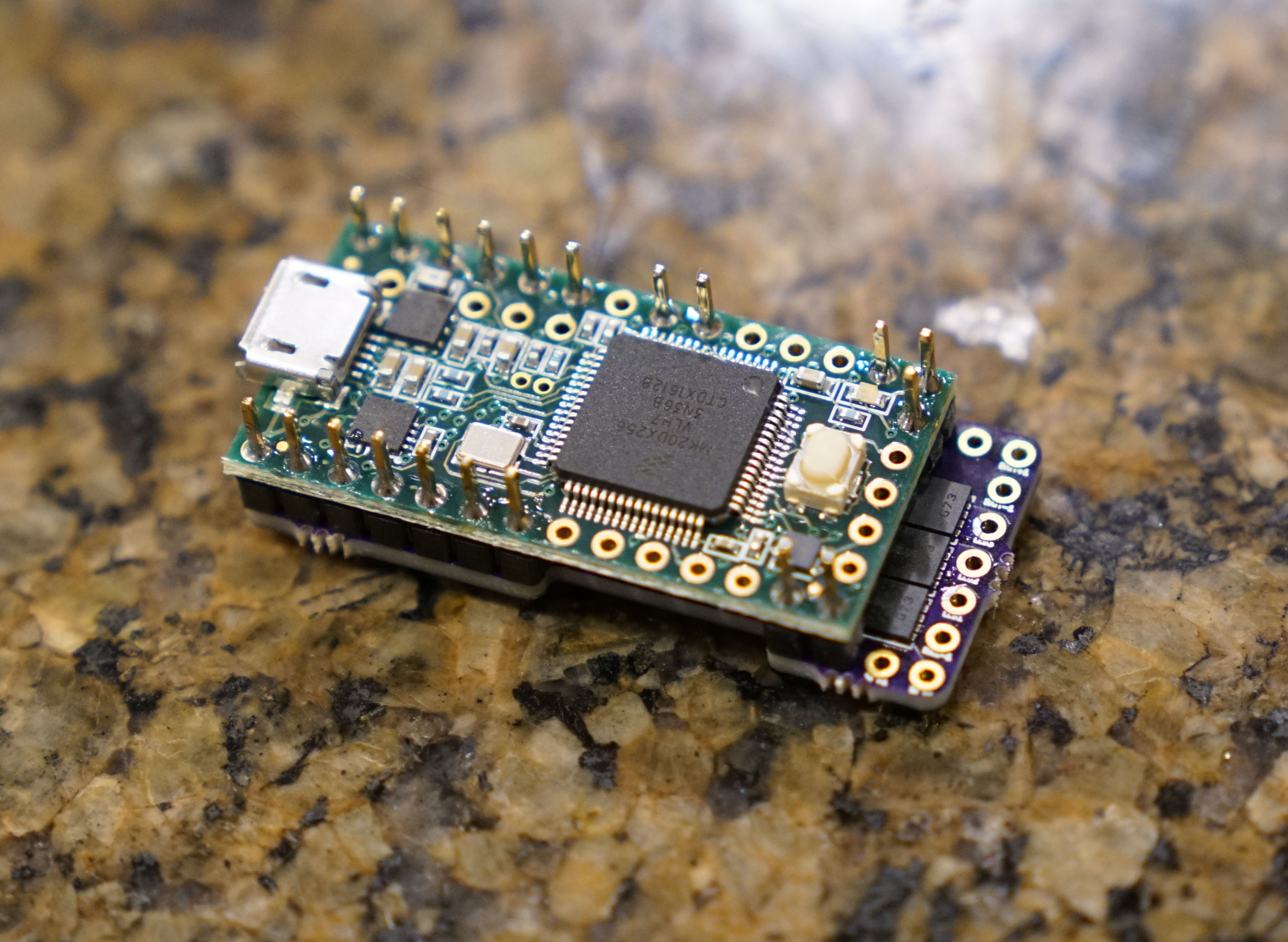
Anyways, put the teensy 3.2 on top and solder the pins/wires into place. (top and bottom)
Later, we'll cut or bend the pins to make sure they aren't in the way.
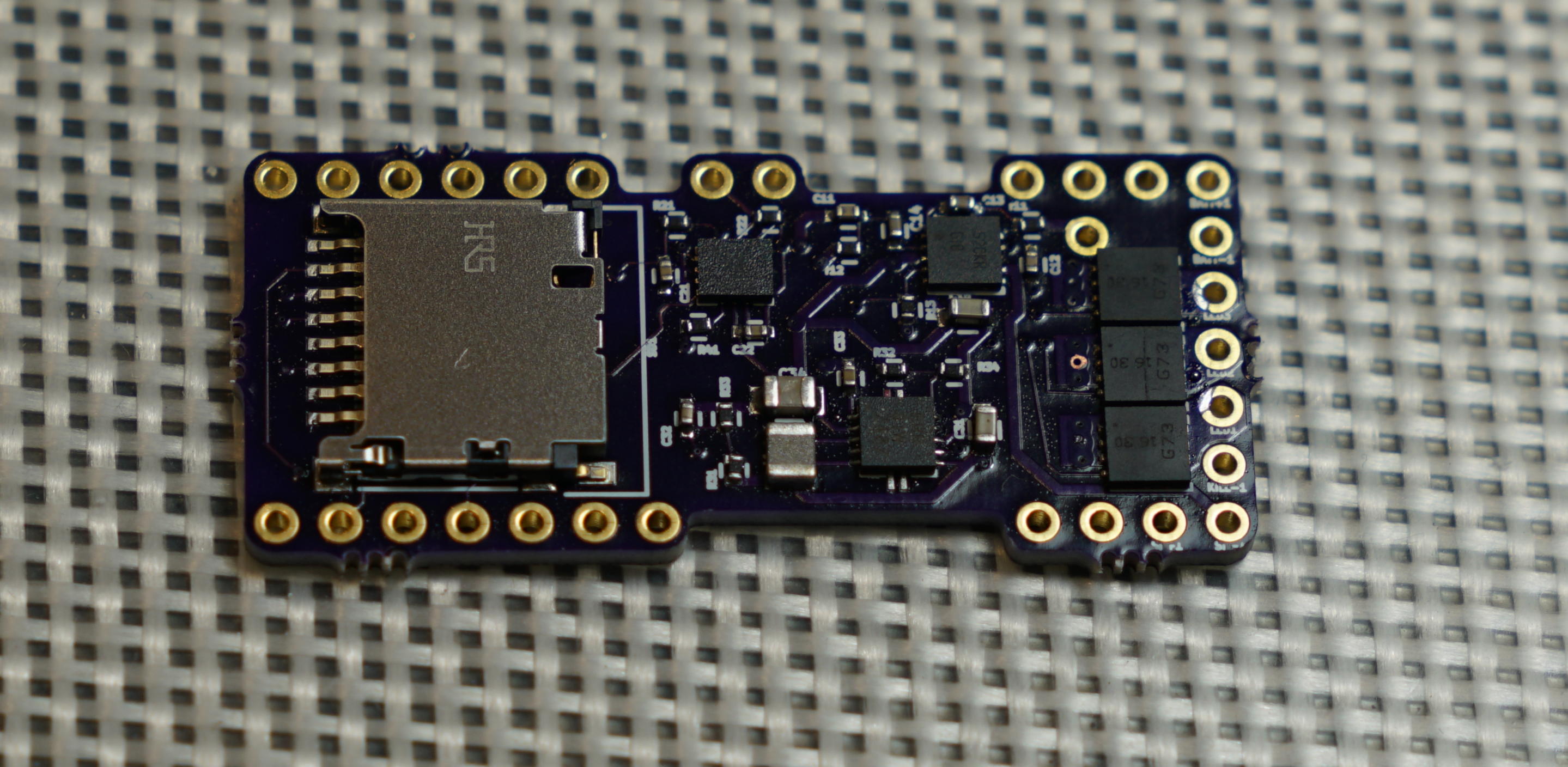
When you're done, it should look something like this:
Pinout
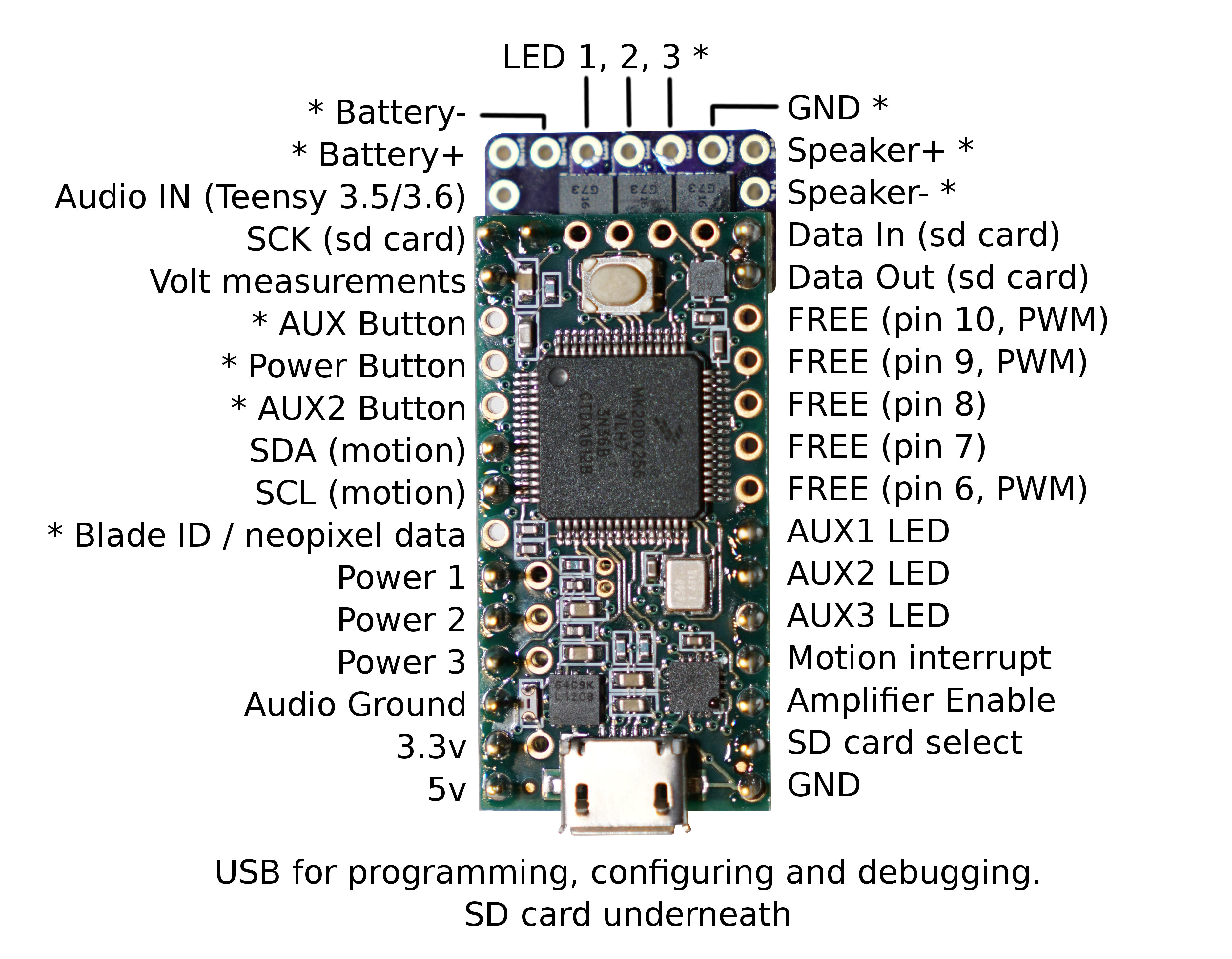 Note: Pins marked with * are ones that you probably want to hook up to something. The rest of the pins are usually ignored.
- Battery+ - 2.6 to 4.5 volt input, drives everything except the LEDs
- Battery- - negative pad for LEDs, needs to be at same level as GND when both are connected.
- GND - ground for electronics except LEDs
- Speaker +/- - hooks up to speaker
- Power, Aux, Aux 2 - Hook up to closing buttons, or potentially touch buttons.
- Blade ID / neopixel data - Normally used to measure the blade ID restor, and if it's a neopixel blade, feed out neopixel data. For a fixed non-neopixel saber, it could be repurposed.
- LED 1, 2, 3 - Hooks up to negative side of LED (positive side of LED hooks up directly to battery.) These pads can handle up to 30 volts.
- Power 1, Power 2, Power 3 - These control the FETs which drive LED 1, 2, 3.
- AUX LED 1, 2, 3 - These are hooked up to pads on the bottom which can be populated with FETs and used to drive additional LEDs. If the bottom FETs are not populated, these pins are free and can be used for any purpose.
- Free pins - these are not used for anyting and could be hooked up as additional inputs or outputs. Pins marked with "PWM" have hardware PWM support which can be used to control the brightness of LEDs or drive servos.
- Data In, Data Out, SCK, SD card select - these pins are used to communicate with the SD card.
- SDA, SCL, Motion Interrupt - these pins are used to communicate with the gyro and accelerometer chip.
- Volt measurements - used to read battery voltage.
- Audio IN - There are two of these pins, one is to the right of SCK and is normally used to connect to the A14 on a Teensy 3.2. The other one is between Battery+ and SCK, and is used to A22 on a Teensy 3.5 or 3.6.
- Amplifier enable - Used to control the amplifier.
- 5v - generated by the TeensySaber board.
- 3.3v - generated by the Teensy
Wire gauges
Most pads on the teensy will not need to carry any significant amount
of power and can use 30 awg (very thin) wire if you choose.
However, Battery- will carry the combined power of all your LEDs, and LED 1,2,3 (and 4,5,6 on the bottom) will carry a fair amount of power as well. It is recommended to use thicker wires, for these wires. There is no absolute rules for what wire guages are required, but here is a helpful chart. (See the "chassis wiring" column.) Keeping the high-power wires short helps as well.
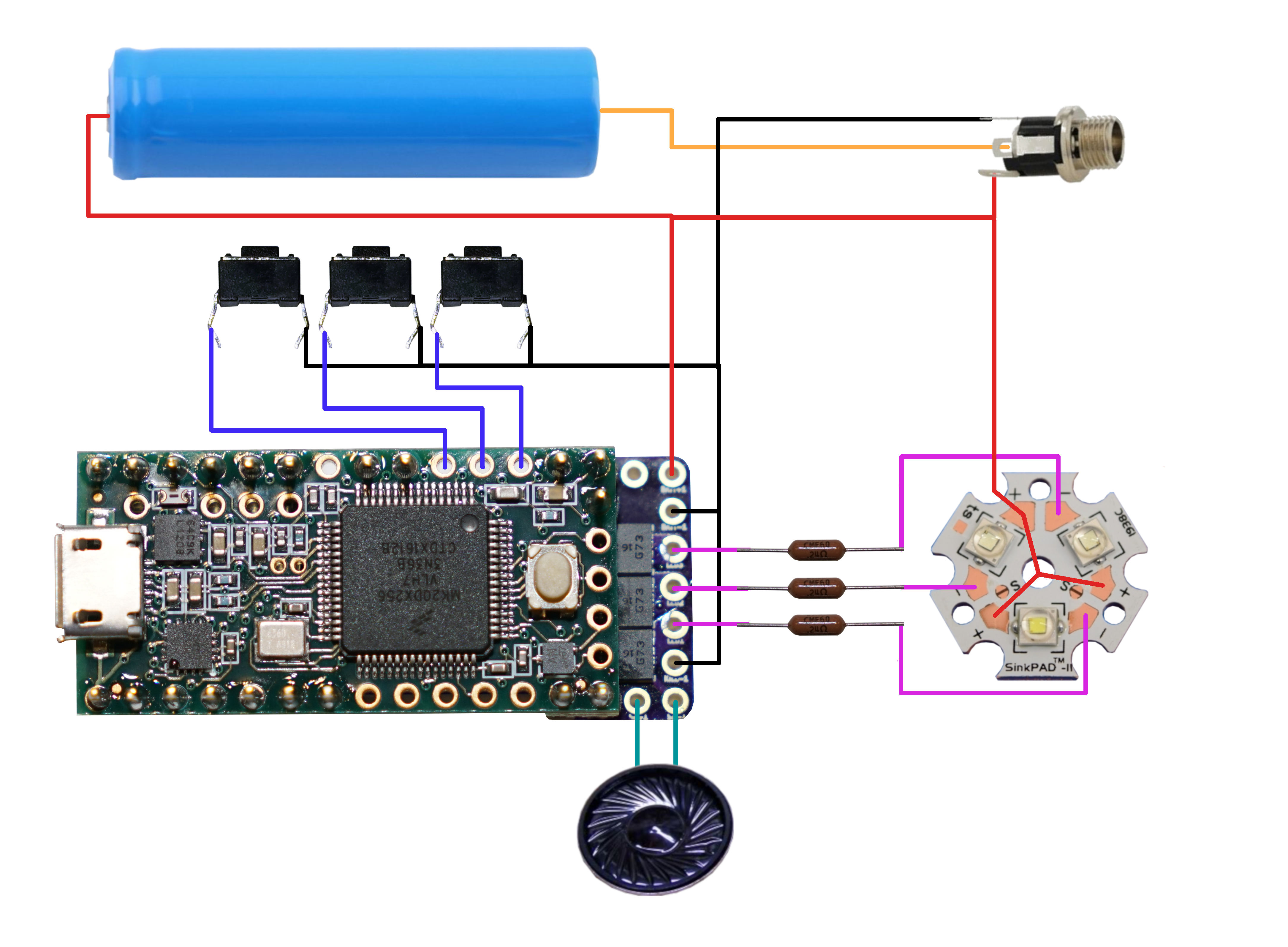
Basic saber circuit diagram
Here is an example of how to hook up a TeensySaber with 2.1mm charge port and an LED star.
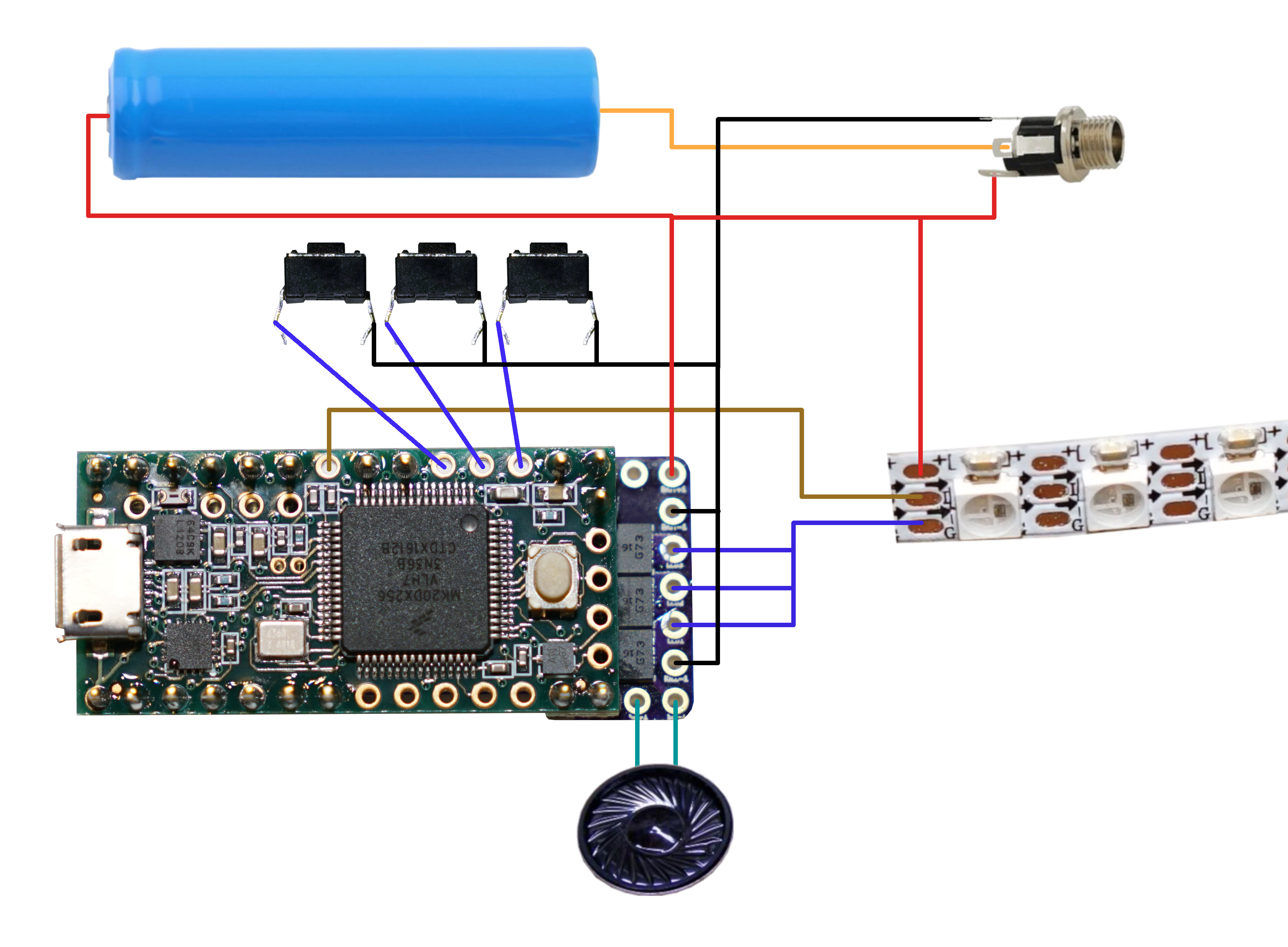
Neopixel / WS2811 saber circuit diagram
Here is an example of how to hook upu a TeensySaber with 2.1mm charge port and an neopixel LED strip.
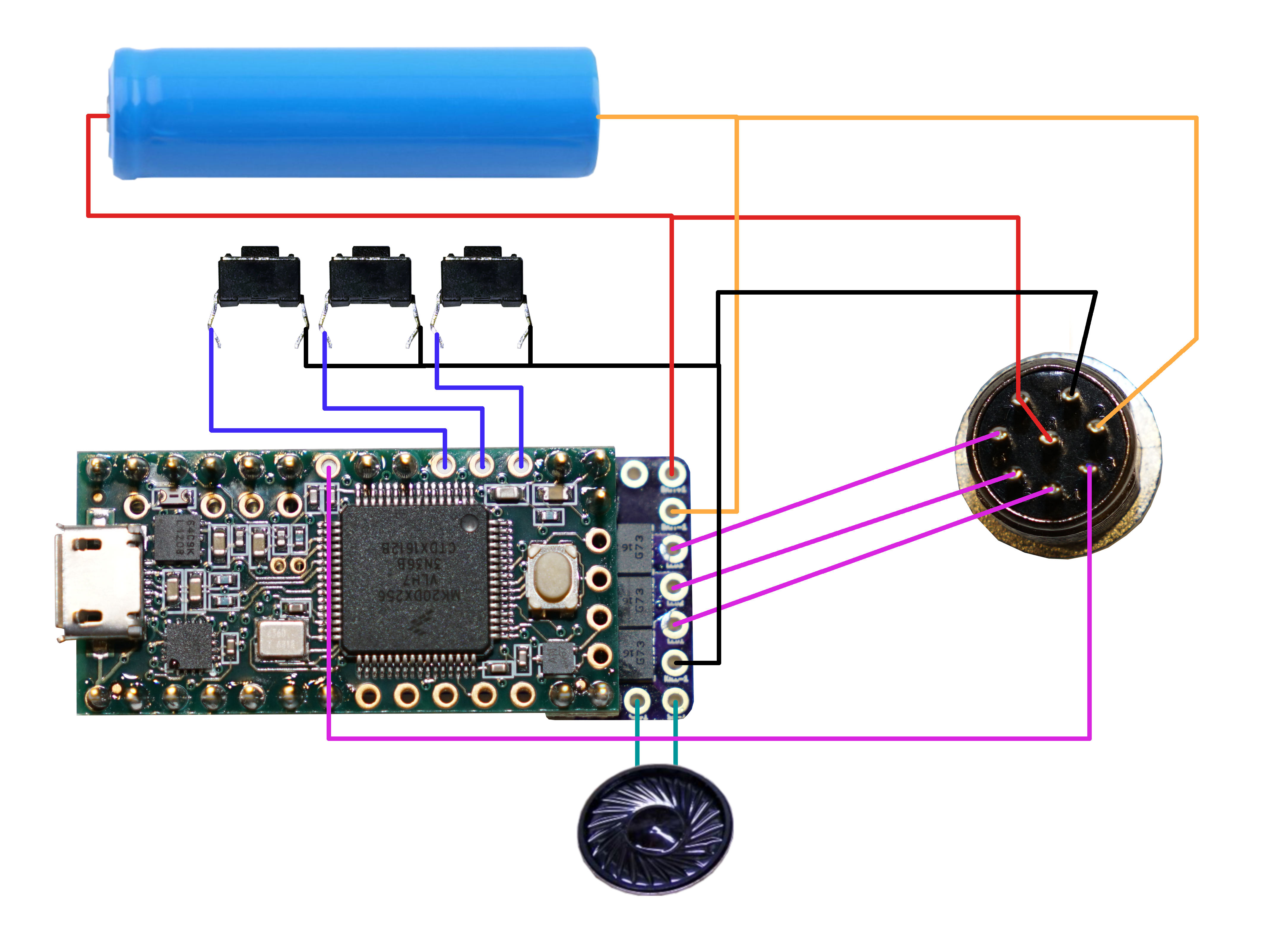
Blade connector circuit diagram
This is how I hook up my TeensySaber to an 8-pin aviation connector, which lets me use
LED stars, string blades and neopixels with the same hilt. I can also charge the battery through this connector.
The blades use a resistor to identify themselves so that the TeensySaber code
can activate the blade in the right way.
 In the blade, these are the connections you would make:
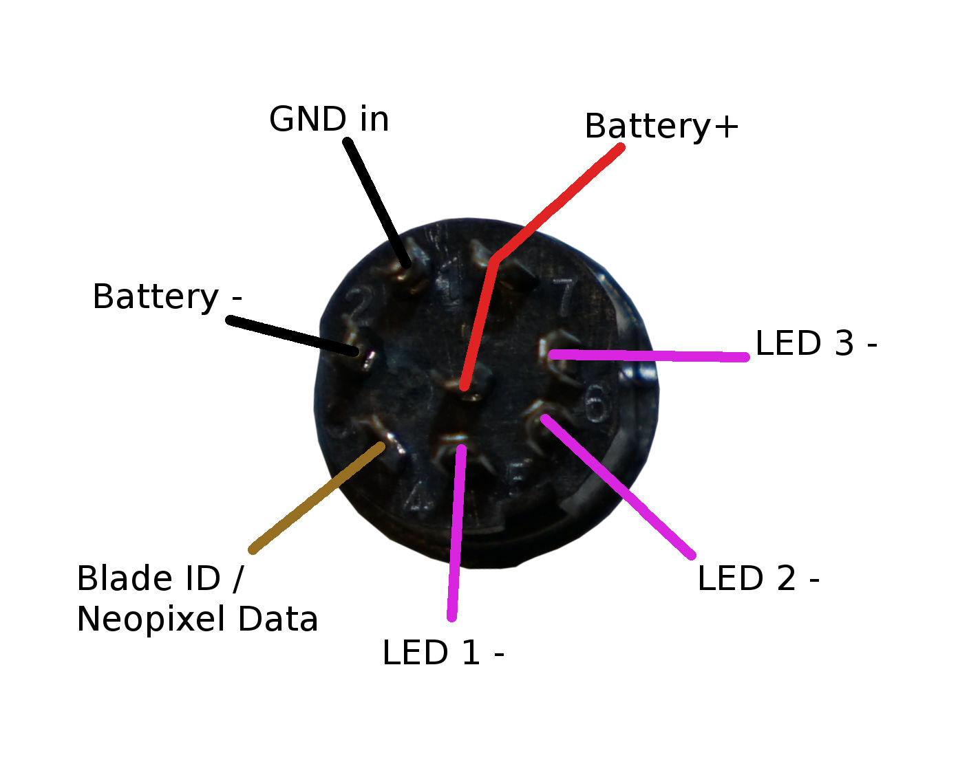 Note that the two connectors are mirror-image when you look at them from behind.
- Normally Battery- is connected to GND in, as that will power the electronics. (LED power does not go thorugh this connector though.)
- Blade id should be connected through a resistor to Battery- / GND. The teensysaber code will identify the blade by measuring the resistor. Useful values range from 10 ohms to 100kOhms, Each resistor should be at least 20% different from all your other blades though.
- LED 1,2,3 are controlled by FETs. LEDs should be connected between Battery+ and one or more of the LED pins. (Usually with a resistor to lower the voltage.)
- Battery+ is connected to the positive side of the battery.
Touch Buttons
Any of the buttons can replaced with a touchbutton.
To wire a touchbutton, simply hook up the corresponding wire to a metal surface. Note that in spite of the name, you don't
actually want anybody to actuall touch the touch-buttons. The metal surface needs to be insulated, both from the
rest of the hilt, and from the fingers that will be "touching" it. In my case, I used a circut-board clamp card in a Graflex
lightsaber, then I covered it up with tape to insulate it from everything else.
More details here.
Choosing Resistors
Calculating resistor values is fairly easy. Just look up how many amps the LED can handle and at what voltage it expects to achive that current. Then the resitor value we want is (BatteryVoltage - LedVoltage) / LedAmps. And the resistor needs to handle (BatteryVoltage - LedVoltage) * LedAmps watts. Example, if the LED wants 1A @ 3.2 volts, the resistor would be (3.7 - 3.2)/1 = 0.5 ohms, (3.7 - 3.2) * 1 = 0.5 watts.
Note that I use 3.7 volts for the battery in these calculations, while li-ion batteries tends to top out at 4.2 volts.
TeensySaber can compensate for this by using PWM to reduce the total amount of power and heat generated by the LED when
the voltage is higher than what it is rated for. This mode is efficient and seems to work well, but it is possible that it
will reduce the life of the LEDs. If you are not comfortable with this, you should use 4.1 or 4.2 volts in the calculations above.
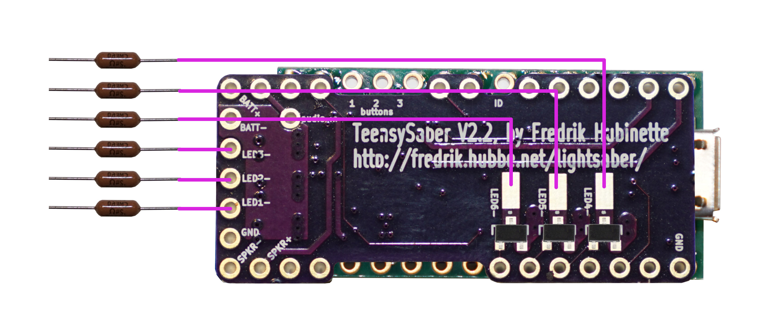
AUX Leds and LED strings
The bottom of the TeensySaber board has room for three SOT-23 FETs, these are fairly easy to solder by hand, and can be used
to control three more sets of LEDs. This can either be used to control auxiliary LEDs, or to control segments of a segmented
LED string. Once I actually do this myself, I will add pictures and more information about how to do this. Here is a partial circuit diagram:
Multi-battery setup
The FETs on the teensysaber can handle voltages up to 30v, so it's possible to do multi-cell setups. However, "Battery+" cannnot handle more than ~4.5 volts. So you would need a separate battery to power the teensy electronics. Another possibility would be to do two batteries in series, but only use one of them to power the teensy. Since the batteries would be discharged unevently, they would have to be charged separately. In the future, I hope to make "Battery+" handle a wider range of voltages, which would make multi-cell configurations a lot simpler.
Troubleshooting
If you're having problems, check out the troubleshooting page.
Problems? Questions? Suggestions? Check out The Crucible.
This page has been accessed 28,279 times since
February
11th,
2017.
Last modified:
March
29th,
2021
- Design by
Monica &
Fredrik
Hübinette
|
|
|
|
|